What is an Electrical Switch :
An electrical switch is any device used to interrupt the flow of electrons in a circuit. Switches are essentially binary devices: they are either completely on (“closed”) or completely off (“open”). There are many different types of switches, and we will explore some of these types in this chapter.
Learn the Different Types of Switches :
Switches can be of mechanical or electronic type,
Mechanical switches must be activated physically, by moving, pressing, releasing, or touching its contacts.
Electronic switches do not require any physical contact in order to control a circuit. These are activated by semiconductor action.
Mechanical Switches :
Mechanical switches can be classified into different types based on several factors such as method of actuation (manual, limit and process switches), number of contacts (single contact and multi contact switches), number of poles and throws (SPST, DPDT, SPDT, etc.), operation and construction (push button, toggle, rotary, joystick, etc), based on state (momentary and locked switches), etc.
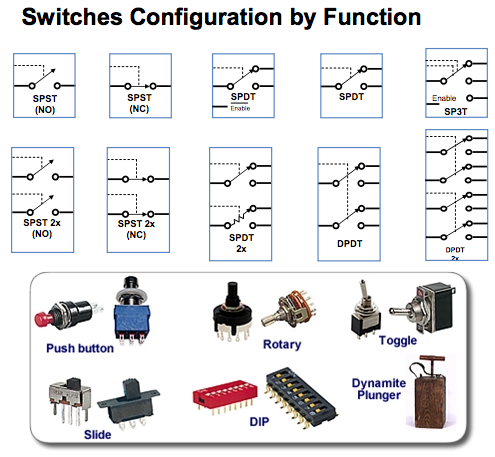
Based on the number of poles and throws, switches are classified into following types. The pole represents the number of individual power circuits that can be switched. Most of the switches are designed have one, two or three poles and are designated as single pole, double pole and triple pole.
The number of throws represents the number of states to which current can pass through the switch. Most of the switches are designed to have either one or two throws which are designated as single throw and double throw switches.
Single Pole Single Throw Switch (SPST) :
 This is the basic ON and OFF switch consisting of one input contact and one output contact.
- It switches a single circuit and it can either make (ON) or break (OFF) the load.
- The contacts of SPST can be either normally open or normally closed configurations .
Single Pole Double Throw Switch (SPDT) :
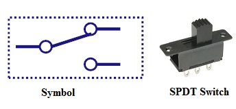 This switch has three terminals,one is input contact and remaining two are output contacts.
- This means it consist two ON positions and one OFF position.
- In most of the circuits, these switches are used as changeover to connect the input between two choices of outputs.
- The contact which is connected to the input by default is referred as normally closed contact and contact which will be connected during ON operation is a normally open contact.
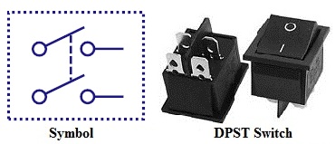
Double Pole Single Throw Switch (DPST) :
- This switch consists of four terminals,two input contacts and two output contacts.
- It behaves like a two separate SPST configurations, operating at the same time.
- It has only one ON position, but it can actuate the two contacts simultaneously, such that each input contact will be connected to its corresponding output contact.
- In OFF position both switches are at open state.
- This type of switches is used for controlling two different circuits at a time.
- Also, the contacts of this switch may be either normally open or normally closed configurations.
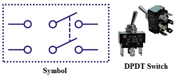
Double Pole Double Throw Switch (DPDT) :
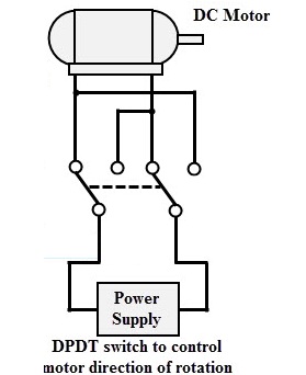 This is a dual ON/OFF switch consisting of two ON positions.
- It has six terminals,two are input contacts and remaining four are the output contacts.
- It behaves like a two separate SPDT configuration, operating at the same time.
- Two input contacts are connected to the one set of output contact is in one position and in another position, input contacts are connected to the other set of output contacts.
Push Button Switch :
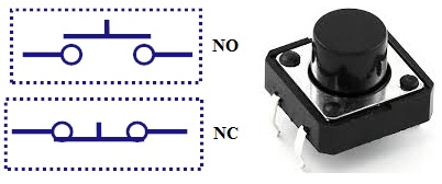
- It is a momentary contact switch that makes or breaks connection as long as pressure is applied (or when the button is pushed).
- Generally, this pressure is supplied by a button pressed by someone’s finger.
- This button returns its normal position, once the pressure is removed.
- The internal spring mechanism operates these two states (pressed and released) of a push button.
- It consists of stationary and movable contacts, of which stationary contacts are connected in series with the circuit to be switched while movable contacts are attached with a push button.
- Push buttons are majorly classified into normally open, normally closed and double acting push buttons as shown in the above figure.
- Double acting push buttons are generally used for controlling two electrical circuits.
 |
| Push Button Switch |
Toggle Switch :
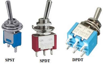
- A toggle switch is manually actuated (or pushed up or down) by a mechanical handle, lever or rocking mechanism. These are commonly used as light control switches.
- Most of these switches come with two or more lever positions which are in the versions of SPDT, SPST, DPST and DPDT switch. These are used for switching high currents (as high as 10 A) and can also be used for switching small currents.
- These are available in different ratings, sizes and styles and are used for different type of applications. The ON condition can be any of their level positions, however, by convention the downward is the closed or ON position.
 |
| Toggle Switch |
Limit Switch :
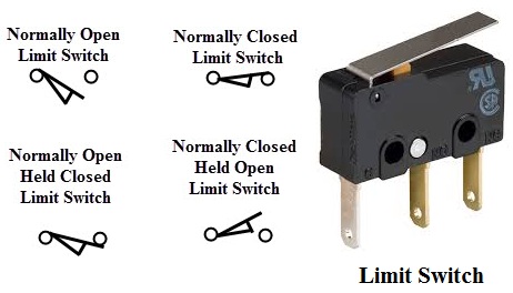 The control schemes of a limit switch are shown in above figure , in which four varieties of limit switches are presented.
- Some switches are operated by the presence of an object or by the absence of objects or by the motion of machine instead of human hand operation. These switches are called as limit switches.
- These switches consist of a bumper type of arm actuated by an object. When this bumper arm is actuated, it causes the switch contacts to change position.
Float Switches :
- Float switches are mainly used for controlling DC and AC motor pumps according to the liquid or water in a tank or sump.
- This switch is operated when the float (or floating object) moves downward or upward based on water level in a tank.
- This float movement of rod or chain assembly and counterweight causes to open or close electrical contacts. Another form of float switch is the mercury bulb type switch that does not consist of any float rod or chain arrangement.
- This bulb consist of mercury contacts such that when the liquid level rises or falls, the state of contacts also changes.
- The ball float switch symbol is shown in the above figure. These float switches can be normally open or normally closed type.
Flow Switches :
- These are mainly used to detect the movement of liquid or air flow through a pipe or duct. The air flow switch (or a micro switch) is constructed by a snap-action.
- This micro switch is attached to a metal arm .To this metal arm, a thin plastic or metal piece is connected.
- When a large amount of air passes through the metal or plastic piece, it causes the movement of metal arm and thus operates the contacts of the switch.
- Liquid flow switches are designed with a paddle that inserted across the flow of liquid in a pipe. When liquid flows through the pipe, force exerted against the paddle changes the position of the contacts.
- The above figure shows the switch symbol used for both air flow and liquid flow. The flag symbol on the switch indicates the paddle which senses the flow or movement of liquid.
- These switches again normally open or normally closed type configurations.
Pressure Switches :
- These switches are commonly used in industrial applications in order to sense the pressure of hydraulic systems and pneumatic devices.
- Depends on the range of pressure to be measured, these pressure switches are classified into diaphragm operated pressure switch, metal bellow type pressure switch and piston type pressure switch.
- In all these types, pressure detection element operates a set of contacts (which can be either double pole or single pole contacts).
- This switch symbol consist a half-circle connected to a line in which flat part indicates a diaphragm. These switches may be either normally open or normally closed type configurations.
Temperature Switches :
- The most common heat sensing element is the bimetallic strip that operates on the principle of thermal expansion.
- The bimetallic strips are made with two dissimilar metals (that are having different thermal expansion rates) and are bonded with each other.
- The switch contacts are operated when the temperature causes the strip to bend or wrap. Another method of operating the temperature switch is to use mercury glass tube.
- When the bulb is heated, mercury in the tube will expand and then generates pressure to operate the contacts.
Joystick Switch :
- Joystick switches are manually actuated control devices used mainly in portable control equipments.
- It consists of a lever which moves freely in more than one axis of motion.
- Depending on the movement of the lever pushed, one or more switch contacts are actuated.
- These are ideally suited for lowering, raising and triggering movements to the left and right.
- These are used for building machinery, cable controls and cranes. The symbol for the joystick is shown below.
Rotary Switches :
- These are used for connecting one line to one of many lines.
- Examples of these switches are range selectors in electrical metering equipment, channel selectors in communication devices and band selectors in multi-band radios.
- It consists of one or more moving contacts (knob) and more than one stationary contact.
- These switches are come with different arrangement of contacts such as single pole 12-way, 3-pole 4-way, 2-pole 6-way and 4-pole 3-way.
Related Post:
1. Electronic Switch
2. Difference Between Voltage & Current
3. What is Current & Voltage
1. Electronic Switch
2. Difference Between Voltage & Current
3. What is Current & Voltage
Comments
Post a Comment
Do not enter any spam link in the comment box.