Introduction to the Amplifiers
An amplifier is used to increase the amplitude of a signal waveform, without changing other parameters of the waveform such as frequency or wave shape. They are one of the most commonly used circuits in electronics and perform a variety of functions in a great many electronic systems.
Amplifiers as Parts of Large Electronic Systems
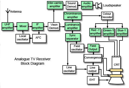
For example look at the block diagram of an analogue TV receiver in Fig 1.0.2 and see how many of the individual stages (shaded green) that make up the TV are amplifiers. Also notice that the names indicate the type of amplifier used. In some cases the blocks shown are true amplifiers and in others, the amplifier has extra components to modify the basic amplifier design for a special purpose. This method of using relatively simple, individual electronic circuits as "building blocks" to create large complex circuits is common to all electronic systems; even computers and microprocessors are made up of millions of logic gates, which are simply specialised types of amplifiers. Therefore to recognise and understand basic circuits such as amplifiers is an essential step in learning about electronics.


Fig . Analogue colour TV receiver block diagram
One way to describe an amplifier is by the type of signal it is designed to amplify. This usually refers to a band of frequencies that the amplifier will handle, or in some cases, the function that they perform within an electronic system.
A.F. Amplifiers
Audio frequency amplifiers are used to amplify signals in the range of human hearing, approximately 20Hz to 20kHz, although some Hi-Fi audio amplifiers extend this range up to around 100kHz, whilst other audio amplifiers may restrict the high frequency limit to 15kHz or less.
Audio voltage amplifiers are used to amplify the low level signals from microphones, tape and disk pickups etc. With extra circuitry they also perform functions such as tone correction equalisation of signal levels and mixing from different inputs, they generally have high voltage gain and medium to high output resistance.
Audio power amplifiers are used to receive the amplified input from a series of voltage amplifiers, and then provide sufficient power to drive loudspeakers.
I.F. Amplifiers
Intermediate Frequency amplifiers are tuned amplifiers used in radio, TV and radar. Their purpose is to provide the majority of the voltage amplification of a radio, TV or radar signal, before the audio or video information carried by the signal is separated (demodulated) from the radio signal. They operate at a frequency lower than that of the received radio signal, but higher than the audio or video signals eventually produced by the system. The frequency at which I.F. amplifiers operate and the bandwidth of the amplifier depends on the type of equipment. For example, in AM radio receivers the I.F. amplifiers operate at around 470kHz and their bandwidth is normally 10kHz (465 kHz to 475kHz), while TV commonly uses 6Mhz bandwidth for the I.F. signal at around 30 to 40MHz, and in radar a band width of 10 MHz may be used.


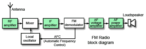
Fig. FM Radio using AF, IF and RF amplifiers.
R.F. Amplifiers
Radio Frequency amplifiers are tuned amplifiers in which the frequency of operation is governed by a tuned circuit. This circuit may or may not, be adjustable depending on the purpose of the amplifier. Bandwidth also depends on use and may be relatively wide, or narrow. Input resistance is generally low, as is gain. (Some RF amplifiers have little or no gain at all but are primarily a buffer between a receiving antenna and later circuitry to prevent any high level unwanted signals from the receiver circuits reaching the antenna, where it could be re-transmitted as interference). A special feature of RF amplifiers where they are used in the earliest stages of a receiver is low noise performance. It is important that background noise generally produced by any electronic device, is kept to a minimum because the amplifier will be handling very low amplitude signals from the antenna (µV or smaller). For this reason it is common to see low noise FET transistors used in these stages.
Ultrasonic Amplifiers
Ultrasonic amplifiers are a type of audio amplifier handling frequencies from around 20kHz up to about 100kHz; they are usually designed for specific purposes such as ultrasonic cleaning, metal fatigue detection, ultrasound scanning, remote control systems etc. Each type will operate over a fairly narrow band of frequencies within the ultrasonic range.
Wideband Amplifiers
Wideband amplifiers must have a constant gain from DC to several tens of MHz. They are used in measuring equipment such as oscilloscopes etc. where there is a need to accurately measure signals over a wide range of frequencies. Because of their extremely wide bandwidth, gain is low.
DC Amplifiers
DC amplifiers are used to amplify DC (0Hz) voltages or very low frequency signals where the DC level of the signal is important. They are common in many electrical control systems and measuring instruments.
Video Amplifiers
Video amplifiers are a special type of wide band amplifier that also preserve the DC level of the signal and are used specifically for signals that are to be applied to CRTs or other video equipment. The video signal carries all the picture information in TV, video and radar systems. The bandwidth of video amplifiers depends on use. In TV receivers it extends from 0Hz (DC) to 6MHz and is wider still in radar.
Buffer Amplifiers
Buffer amplifiers are a commonly encountered, specialised amplifier type that can be found within any of the above categories, they are placed between two other circuits to prevent the operation of one circuit affecting the operation of the other. (They ISOLATE the circuits from each other). Often buffer amplifiers have a gain of one, i.e. they do not actually amplify, so that their output is the same amplitude as their input, but buffer amplifiers have a very high input impedance and a low output impedance and can therefore be used as an impedance matching device. This ensures that signals are not attenuated between circuits, as happens when a circuit with a high output impedance feeds a signal directly to another circuit having a low input impedance.
Operational Amplifiers

Operational amplifiers (Op−amps) have developed from circuits designed for the early analogue computers where they were used for mathematical operations such as adding and subtracting. Today they are widely used in integrated circuit form where they are available in single or multiple amplifier packages and often incorporated into complex integrated circuits for specific applications.
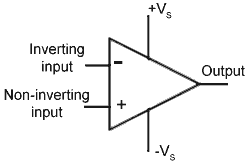
The design is based on a differential amplifier, which has two inputs instead of one, and produces an output that is proportional to the difference between the two inputs. Without negative feedback, op amps have an extremely high gain, typically in the hundreds of thousands. Applying negative feedback increases the op amp´s bandwidth so they can operate as wideband amplifiers with a bandwidth in the MHz range, but reduces their gain. A simple resistor network can apply such feedback externally and other external networks can vary the function of op−amps.
Operational amplifiers (Op−amps) have developed from circuits designed for the early analogue computers where they were used for mathematical operations such as adding and subtracting. Today they are widely used in integrated circuit form where they are available in single or multiple amplifier packages and often incorporated into complex integrated circuits for specific applications.
Comments
Post a Comment
Do not enter any spam link in the comment box.