Difference between Step-up and Step-down transformer
A transformer is a static device which transfers a.c electrical power from one circuit to the other at the same frequency, but the voltage level is usually changed. For economical reasons, electric power is required to be transmitted at high voltage whereas it has to be utilized at low voltage from a safety point of view. This increase in voltage for transmission and decrease in voltage for utilization can only be achieved by using a step-up and step-down transformer.
The major difference between step-up and step-down transformer is, step-up transformer raises the output voltage, whereas step-down transformer reduces the output voltage. Some other differences are explained below, in the form of a comparison chart, considering the factors: voltage, winding, the number of turns, thickness of conductor and application.
Content: Step-up Vs Step-down transformer
Comparison Chart
| BASIS FOR COMPARISON | STEP-UP TRANSFORMER | STEP-DOWN TRANSFORMER |
|---|---|---|
| Definition | Step-up transformer increase the output voltage. | Step-down transformer reduces the output voltage. |
| Voltage | Input voltage is low while the output voltage is high. | Input voltage is high while the output voltage is low. |
| Winding | High voltage winding is the secondary winding. | High voltage winding is the primary winding. |
| Current | Current is low on the secondary winding. | Current is high on the secondary winding. |
| Rating of output voltage | 11000 volts or above | 110v ,24v, 20v, 10v, etc. |
| Size of the conductor | Primary winding is made up of thick insulated copper wire. | Secondary winding is made up of thick insulated copper wire |
| Application | Power plant, X-rays machine, microwaves, etc. | Doorbell, voltage converter, etc. |
Definition of Step-up transformer:
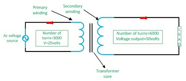
When the voltage is raised on the output side, the transformer is called the step-up transformer. In this transformer, the number of turns in the secondary winding is always greater than the turns in the primary winding because a high voltage is developed on the secondary side of a transformer.
In countries like India, usually, power is generated at 11kv. For economical reasons, a.c.power is transmitted at very high voltages (220v-440v) over long distances. Therefore a step-up transformer is applied at the generating Station.
Step up transformer
Definition of Step-down transformer:
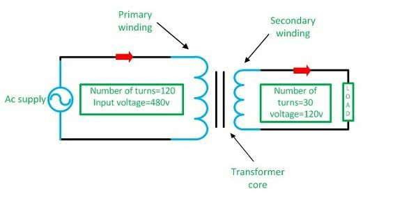
A step-down transformer reduces the output voltages or in other words, it converts high voltage, low current power into a low voltage, high current power. For example, our power circuit carries 230-110v, but the doorbell requires only 16v. So, a step-down transformer should be used to reduce the voltage from 110v or 220v to 16v.
For feeding different areas, voltages are stepped down to 440v/230v for safety reasons.Thus, the number of turns on secondary winding is less than the primary winding so; less voltage is induced at the output (secondary) end of the transformer.
Step down transformer
Key Differences between Step-up transformer and Step-down transformer
- When the output (secondary) voltage is greater than its input (primary) voltage, it is called a step-up transformer, whereas, in step-down transformer output (secondary) voltage is less.
- In a step-up transformer, the low voltage winding is the primary winding, and high voltage winding is the secondary winding, whereas, in step-down transformer, low voltage winding is the secondary winding.
- In a step-up transformer, the current and magnetic field is less developed in the secondary winding, and it is highly developed in the primary winding, whereas, in Step-down transformer, voltage is low on secondary end Thus, the current and magnetic field is high.
- Note1: The current is directly proportional to the magnetic field.
- Note2: According to Ohm’s laws, voltage is directly proportional to the current.If we increase the voltages than current will also increase.But in transformer for transferring the same amount of power, If we increase the voltage the current will decrease and vice versa. So the power remains the same in the sending and receiving ends of a transformer.
- In a step-up transformer, the primary winding is made up of thick insulated copper wire, and the secondary is made up of thin insulated copper wire, whereas, in step-down transformer the output current is high so, the thick insulated copper wire is used for making secondary winding.
- Note: Thickness of wire depends upon the capacity of current flow through them.
- Step-up transformer extends the voltages from 220v-11kv or above, whereas, step-down transformer reduces the voltages from 440-220v,220-110v or 110-24v,20v,10vetc.
Point to Remember:
The Same transformer can be used as a step-up or a step-down transformer. It depends upon the ways in which it is connected in the circuit. If input supply is given on the low voltage winding, then it becomes a step-up transformer. Alternately, if the input supply is provided on the high voltage winding, the transformer becomes a step-down one.


Comments
Post a Comment
Do not enter any spam link in the comment box.