How To Use Transistor As A Switch
The transistor was invented by “William Shockley” in 1947. A transistor is a three terminal semiconductor device which can be used for switching applications, amplification of weak signals and in quantities of thousands and millions of transistors are interconnected and embedded into a tiny integrated circuit/chip, which makes computer memories. A Transistor switch, which is used for opening or closing of a circuit, that means the transistor is commonly used as a switch in the electronic devices only for the low voltage applications because of its low power consumption.Transistor work as a switch when it is in cutoff and saturation regions. In this article, we will discuss how to use a transistor as a switch.
 |
| Transistor |
Types of BJT transistors :
Basically, a transistor consists of two PN junctions, these junctions are formed by sandwiching either N-type or P-type semiconductor material between a pair of opposite type of semiconductor materials.
Bipolar junction transistor are classified into two types
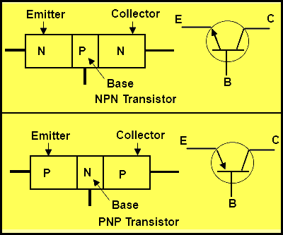
- NPN
- PNP
 |
| Transistor System |
The transistor has three terminals, namely Base, Emitter, and Collector. The emitter is a heavily doped terminal and it emits the electrons into the Base region. The Base terminal is lightly doped and passes the emitter-injected electrons onto the collector. The collector terminal is intermediately doped and collects electrons from the Base.
An NPN type transistor is the composition of two N-type doped semiconductor materials between a P-type doped semiconductor layer as shown above. Similarly, A PNP-type transistors are the composition of two P-type doped semiconductor materials between an N-type doped semiconductor layer as shown above. The functioning of both NPN and PNP transistor is same but differ in terms of their biasing and power supply polarity.
If the circuit uses the BJT transistor as a switch, then the biasing of the transistor, either NPN or PNP is arranged to operate the transistor at the both sides of the I-V characteristics curves shown below. A transistor can be operated in three modes, active region, saturation region and cut-off region. In the active region, transistor works as an amplifier. The two operating regions of transistor Saturation Region (fully-ON) and the Cut-off Region (fully-OFF) were used to operate a transistor switch.
Operating Regions :
We can observe from the above characteristics, the pink shaded area at the bottom of the curves represents the Cut-off region and the blue area to the left represent the Saturation region of the transistor. these transistor regions are defined as
 |
| VI - Characteristics |
Cut-off Region :
The operating conditions of the transistor are zero input base current (IB=0), zero output collector current(Ic=0), and maximum collector voltage (VCE) which results in a large depletion layer and no current flowing through the device. Therefore the transistor is switched to “Fully-OFF”. So we can define the cut-off region when using a bipolar transistor as a switch as being, bother the junctions of NPN transistors are reverse biased, VB< 0.7v and Ic=0. Similarly, for PNP transistor, the emitter potential must be –ve with respect to the base of the transistor.
 |
| Cut - Off Region |
Then we can define the “cut-off region” or “OFF mode” when using a bipolar transistor as a switch as being, both junctions reverse biased, IC = 0 and VB < 0.7v. For a PNP transistor, the Emitter potential must be -ve with respect to the Base.
In this region, the transistor will be biased so that the maximum amount of base current(IB) is applied, resulting in maximum collector current(IC=VCC/RL) and then resulting in the minimum collector-emitter voltage(VCE ~ 0) drop. At this condition, the depletion layer becomes as small as the possible and maximum current flowing through the transistor. Therefore the transistor is switched “Fully-ON”.
 |
| Saturation Region |
The definition of “saturation region” or “ON mode” when using a bipolar NPN transistor as a switch as being, both the junctions are forward biased, IC = Maximum and VB > 0.7v. For a PNP transistor, the Emitter potential must be +ve with respect to the Base.
Some of the basic Applications of Transistor as a Switch
In a transistor, unless a current flows in the base circuit, there is no current can flow in the collector circuit. This property will allow a transistor to be used as a switch. The transistor can be switched ON or OFF by changing the base. There are a few applications of switching circuits operated by transistors. Here, I considered NPN transistor to explain few applications which are using transistor switch.
Light-Operated Switch :
The circuit is designed by using a transistor as a switch, to light the bulb in a bright environment and to turn it off in the dark and a Light Dependent Resistors LDR In the potential divider. When the environment dark LDR’s resistance become high. Then the transistor is switched OFF. When the LDR is exposed to the bright light, its resistance falls to less value resulting in more supply voltage and raising the base current of the transistor. Now the transistor is switched ON, the collector current flows and bulb lights up.
 |
| Light - Operated Switch |
Heat Operated Switch :
One important component in the circuit of a heat-operated switch is the thermistor. The thermistor is a type of resistor that responds depending upon the surrounding temperature. Its resistance increases when the temperature is low and vice versa. When heat is applied to the thermistor, its resistance drops and the base current increases followed by a greater increase in the collector current and the siren will blow.
 |
| Heat - Operated Switch |
DC Motor Control (driver) in the Case of High Voltages
Consider no voltage is applied to the transistor, then the transistor becomes OFF and no current will flow through it. Hence the relay. remains in OFF state. Power to the DC Motor is fed from the Normally Closed (NC) terminal of the relay, so the motor will rotate when the relay is in OFF state. Apply of high voltage at the base of transistor BC548 causes turning ON of the transistor and the relay coil to energize.
 in the Case of High Voltages") |
| DC Motor Control (driver) in the Case of High Voltages |
Comments
Post a Comment
Do not enter any spam link in the comment box.