Various Types Of Diodes With Their Characteristics & Uses
The diode is the most used semiconductor device in electronics circuits. It is a two-terminal electrical check valve that allows the flow of current in one direction. They are mostly made up of silicon but germanium is also used. Usually, they are used for rectification. But there are different properties & characteristics of diodes which can be used for different application. These characteristics are modified to form different types of diodes. Nowadays, several different types of diodes having different properties are available.
P-N Junction Diode :
The P-N junction diode is made up of semiconductor material. It consists of two layers of semiconductors. One layer is doped with P-type material and the other layer with N-type material. The combination of these both P and N-type layers form a junction known as the P-N junction. Hence the name P-N junction diode.
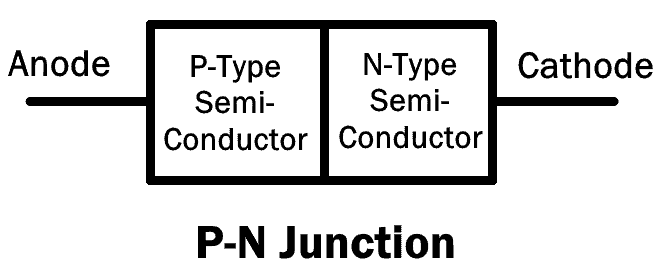
It allows the flow of current in the forward direction and blocks it in reverse direction. They are also known as rectifier diode used for rectification.
There are different types of diodes that use the P-N junction with variation in doping concentration. They are discussed below.
Small Signal Diode :
It is a type of P-N junction diode which operates on low voltage signals. Its junction area is very small. Due to which, the junction has less capacitance & low charge storing capacity. It enables the small signal diode to have high switching speed with very fast recovery time. However, its limitations are low voltage and current parameters.
Due to its high switching speed, these types of diodes are used in circuits with high frequencies.
Rectifier Diode :
A rectifier diode is a type of P-N junction diode, whose P-N junction area is very large. This results in high capacitance in reverse direction. It has low switching speed.
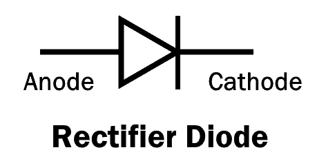
This is the most common and most used type of a diode. These types of diodes can handle heavy current and are used in converting AC into DC (Rectification).
Schottky Diode :
The Schottky diode, named after a German physicist Walter H. Schottky, is a type of diode which consists of a small junction between an N-type semiconductor and a metal. It has no P-N junction.
The plus point of the Schottky diode is that it has very low forward voltage drop and fast switching. As there is no capacitive junction (P-N junction), the Schottky diode switching speed is very fast.
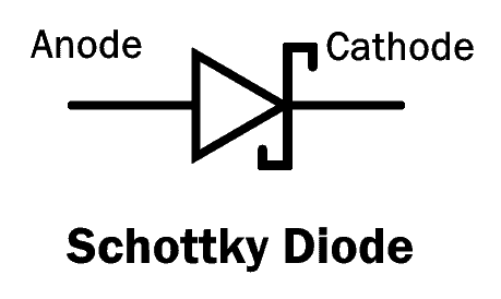
The limitation of Schottky diode is that it has low reverse breakdown voltage and high reverse leakage current.
Super Barrier Diode :
Super barrier diodes (SBR) are also rectifier diodes but they have a low forward voltage drop just like a Schottky diode. They have low reverse leakage current just like a normal P-N junction diode.
SBR uses MOSFET by making short contact between its gate and source.
SBR has a low forward voltage drop, less reverse leakage current and fast switching capability.
Light Emmiting Diode (LED) :
The light emitting diode is also a type of P-N junction diode that emits light in the forward bias configuration.
LED is made up of a direct-band semiconductor. When the charge carriers (electrons) cross the barrier and recombine with electron holes on the other side, they emit photon particles (light). While the color of the light depends on the energy gap of the semiconductor.
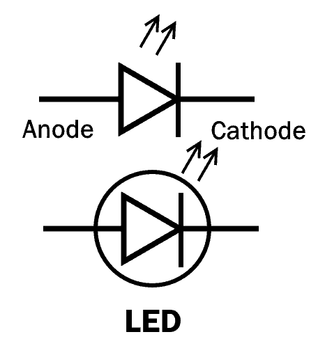
LED converts electrical energy into light energy.
Photodiode :
The photodiode is a type of P-N junction diode that converts the light energy into electrical current. Its operation is opposite to that of an LED.

Every semiconductor diode is affected by optical charge carriers. It is why they are packaged in a light blocking material.
In the photodiode, there is a special opening that allows the light to enter its sensitive part.
When the light (Photon particles) strikes the PN junction, it creates an electron-hole pair. These electron and hole flow out as electrical current. To increase its efficiency, a PIN junction diode is used.
A photodiode is used in reverse bias and they can be used in solar cells.
Laser Diode :
A laser diode is similar to LED because it converts electrical energy into light energy. But unlike LED, Laser diode produces coherent light.

The laser diode consists of a PIN junction, where electron and holes combine together in the intrinsic (I) region. when they combine, it generates a laser beam.
Laser diodes are used in optical communication, laser pointer, CD drives and laser printer etc.
Tunnel Diode :
Tunnel diode was invented by Leo Esaki in 1958 for which he received Nobel prize in 1973, which is why it is also known as Esaki diode.
A tunnel diode is a heavily doped P-N junction diode. It works on the principle of the tunneling effect. Due to heavy doping concentration, the junction barrier becomes very thin. This allows the electron to easily escape through the barrier. This phenomenon is known as tunneling effect.
The Tunnel diode has a region in its VI curve where the current decreases as the voltage increases. This region is known as the negative resistance region. The tunnel diode operates in this region in different applications such as an oscillator and a microwave amplifier.
The symbol with VI characteristic curve of tunnel diode is given below:
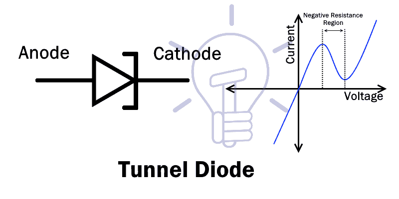
The tunnel diode also conducts current in reverse direction & it is a fast switching device.
Zener Diode :
Zener diode is named after Clarence Malvin Zener who discovered the zener effect.
It is a type of diode, which not only allows the flow of current in the forward direction but also in reverse direction. when the reverse voltage reaches the breakdown voltage known as Zener voltage it allows the current flow.
The Zener diode has heavier doping concentration than a normal P-N junction diode. Hence, it has a very thin depletion region.
In forward bias, it operates as a simple P-N junction diode (Rectifier).
Comments
Post a Comment
Do not enter any spam link in the comment box.