Difference Between Voltage & Current
The voltage and current are the two major aspects of electricity.The voltage is the type of the electromagnetic force whose effect causes the flow of electrical current in the circuit. The magnitude of a voltage and current depends on each other, but these two terms are different from each other in some ways.
One of the major differences between voltage and current is that the voltage is the difference between the two points and the current is the flow of electrical charges between these two points of an electric field. Some others differences between them are explained below in the comparison chart.
Content: Voltage Vs Current :
- Comparison Chart
- Definition
- Key Differences
- Conclusion
Comparison Chart :
| Basis for Comparison | Voltage | Current |
|---|---|---|
| Definition | Difference between two points of an electric field | Flow of charges between two points |
| Unit | Volt | Ampere |
| Symbol | V | I |
| Formula | 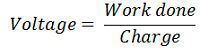 | 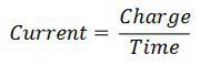 |
| Field Created | Magnetic Field | Electrostatic Field |
| Types | Alternating voltage & Direct voltage | Alternating Current and Direct Current |
| Polarity | Alternating voltage changes, but direct voltage can not change it polarity. | Alternating current change its polarity but the polarity of the direct current remain constant. |
| Produces | Alternator | Voltage |
| Measuring instrument | Voltmeter | Ammeter |
| Charges | 1 Volt = 1 Joule/ Coulomb | 1 Amperes = 1 coulomb /second |
| Series Connection | Unequal in all the components | Equally distributed in all the component |
| Parallel Connection | Magnitude of voltage remain same in all the component | Magnitude of current vary in all the components. |
| Loss | Due to impedance | Due to passive elements |
| Relation | It is the cause of the current | It is the effect of the voltage |
The voltage is the type of the electromagnetic force. When the magnitude of the voltage is high, large current flow through the circuit and when their magnitude is low less current flow through it. The voltage is represented by the symbol V, and their SI unit is volt.
Definition of Voltage :
Voltage is mainly classified into two type, i.e., the alternating voltage and direct voltage. The alternating voltage changes its polarity, and the direct voltage does not change its polarity. The direct voltage is generated by the potential difference between the terminal of the electrochemical cell, and the alternating voltage is caused by the alternator.
 |
| Voltage Circuit Diagram |
Sometimes in a transmission line, the voltage at the sending end is less than the voltage at the receiving end. The voltage is dissipated in the form of the heat and hence this loss of voltage is called voltage drop. The voltage drop occurs because of heavy load. When the heavy load is connected across the line, it draws heavy current due to which voltage loss occurs.
When the receiving end voltage is greater than the sending end voltage, then the voltage rise occurs in the line. The rise in voltage is called Ferranti effect, and it mainly occurs because of the charging current of the transmission line.
Definition of Current :
The current is the effect of the voltage. When the potential difference is applied across the conducting material, the electrical charge carrier starts moving from one atom to another. The current is represented by the symbol I and their SI unit is ampere. The one ampere of current represents the 6.24×10¹⁸ charge carrier. The majority of the charge carriers are negative charge carrier, and the direction of flow of current is from the negative point to relatively positive point.
 |
| Electron Flow |
The electrical current is mainly divided into two types, i.e., the alternating current and direct current. In direct current, the electrons flow only in direction and in alternating current the direction of electrons reversed in every millisecond.
Key Differences Between Voltage and Current :
- The voltage is the difference of the electrical charges between the two point of an electrical field, whereas the current is the flow of the electrical charges between the point of an electrical field.
- The SI (International unit of the standard) unit of the voltage is volts, and the SI unit of the current is amperes.
- The voltage is represented by the symbol V whereas the current is represented by the symbol I.
- The voltage is defined as the ratio of the work done to the charge, whereas the current is the ratio of the charge to the time
- The voltage generates the magnetic field around it whereas the current generates the electrostatic field around it.
- The polarity of the alternating voltage remain changes and due to this alternating voltage, the alternating current induces. But the polarity of the direct voltage remains constant, and their effect induces a direct current.
- The voltage is the difference between the point in an electric field, whereas the current is caused by the flow of the electron in the electrical field.
- The voltage is measured by an instrument called a voltmeter whereas the current is measured by the ammeter.
- The one volt is equal to the 1 joule/coulomb whereas the one ampere is equal to the one column/second.
- In a series circuit, the magnitude of voltage remains different in all the component of the circuit whereas the magnitude of current remains same.
- In the parallel circuit, the voltage at all the branches of the circuit remains same whereas the current is unequally distributed in the circuit component.
- The voltage drop mainly occurs due to the impedance of the circuit whereas the current drop occurs due to the passive element (like a resistor) of the circuit.
- The impedance is the obstruction induces by an electrical circuit to the flow of an electrical current when the potential difference is applied across them.
- The voltage is the cause of the current whereas the current is the effect of the voltage.
Conclusion :
According to ohm’s law, the voltage is directly proportional to the current. The quantitative voltage is generated when the flux is cut by the conductor which is placed between the rotating magnetic field. This voltage induces the current in the circuit. Thus, we can say that the voltage can exist without current, but current cannot exist without voltage. In other words, the current is the effect of the voltage, and the voltage is the cause of the current.
Comments
Post a Comment
Do not enter any spam link in the comment box.