Capacitor Types: Types of Capacitor
There are many different types of capacitor that are used in electronic equipment, each one has its own characteristics: check out the differences and which ones are applicable for different applications.
Polar & non-polar :
One of the main distinctions between various types of capacitor is whether they are polarised.
Essentially a polarised capacitor is one that must be run with the voltage across it in a certain polarity.
 |
| Symbol for polarised capacitor |
Some of the more popular types of polarised capacitor include the aluminium electrolytic and tantalums. These are marked to indicate the positive or negative terminal and they should only be operated with a voltage bias int his direction - reverse bias can damage or destroy them. As capacitors perform many tasks like coupling and decoupling, there will be a permanent DC voltage across them, and they will pass only any AC components.
The other form of capacitor is a non-polarised or non-polar capacitor. This type of capacitor has no polarity requirement and it can be connected either way in a circuit. Ceramic, plastic film, silver mica and a number of other capacitors are non-polar or non-polarised capacitors.
Leaded and surface mount capacitors :
Capacitors are available as leaded varieties and surface mount capacitors. Virtually all types of capacitor are available as leaded versions: electrolytic, ceramic, supercapacitors, plastic film, silver mica, glass and other specialist types.
SMD capacitors are a little more limited. The SMD capacitors must be able to withstand the temperatures used in the soldering process. As the capacitor has no leads and also as a result of the soldering processes used, SMD components including capacitors are exposed tot he full temperature rise of the solder itself. As a result, not all varieties are available as SMD capacitors.
Variable & fixed capacitors :
Another type distinction for capacitors is whether they are fixed or variable.
The greatest majority of capacitors by far are fixed capacitors, i.e. they do not have any adjustment. However in some instances it may be necessary to have an adjustable or variable capacitor where the value of the capacitor may need to be varied. Typically these capacitors are relatively low in value, sometimes having maximum values up to 1000pF.
 |
| A variable capacitor as used for tuning within radios |
Variable capacitors may also be classified as variable and preset. The main variable ones may be adjusted by a control knob and may be used for tuning a radio, etc. Preset variable capacitors normally have a screw adjustment and are intended to be adjusted during setup, calibration and test, etc. They are not intended to be adjusted in normal use.
Fixed capacitor types :
There are very many different fixed value capacitor types that can be bought and used in electronics circuits.
These capacitors are generally categorised by the dielectric that is used within the capacitor as this governs the major properties: electrolytic, ceramic, silver mica, metallised plastic film and a number of others.
While the list below gives some of the major capacitor types, not all can be listed and described and there are some less well used or less common types that can be seen. However it does include most of the major capacitor types.
 |
| Fixed Capacitor |
Ceramic capacitor : As the name indicates, this type of capacitor gains its name from the fact that it uses a ceramic dielectric. This gives the many properties including a low loss factor, and a reasonable level of stability, but this depends upon the exact type of ceramic used. Ceramic dielectrics do not give as high a level of capacitance per unit volume as some types of capacitor and as a result ceramic capacitors typically range in value from a few picofarads up to values around 0.1 µF.
 |
| Ceramic Capacitor |
For leaded components, disc ceramic capacitors are widely used. This type of ceramic capacitor is extensively for applications like decoupling and coupling applications. More highly specified capacitors, especially used in surface mount types of capacitor often have specific types of ceramic dielectric specified. The more commonly seen types include:
- COG: Normally used for low values of capacitance. It has a low dielectric constant, but gives a high level of stability.
- X7R: Used for higher capacitance levels as it has a much higher dielectric constant than COG, but a lower stability.
- Z5U: Used for even higher values of capacitance, but has a lower stability than either COG or X7R.
Ceramic capacitors are available as traditional leaded devices as well feedthrough variants. The most widely used format for ceramic capacitors is as a surface mount capacitor - the format is a multilayer ceramic capacitor also shortened to MLCC. These MLCCs are used in billions every day as they form the most used type fo capacitor for mass production.
Electrolytic capacitor : This type of capacitor is the most popular leaded type for values greater than about 1 microfarad, having the one of the highest levels of capacitance for a given volume. This type of capacitor is constructed using two thin films of aluminium foil, one layer being covered with an oxide layer as an insulator. An electrolyte-soaked paper sheet is placed between them and then the two plates are wound around on one another and then placed into a can.
 |
| Electrolyatic Capacitor |
Electrolytic capacitors are polarised, i.e. they can only be placed one way round in the circuit. If they are connected incorrectly they can be damaged, and in some extreme instances they can explode. Care should also be taken not to exceed the rated working voltage. Normally they should be operated well below this value.
This capacitor type has a wide tolerance. Typically the value of the component may be stated with a tolerance of -50% +100%. Despite this they are widely used in audio applications as coupling capacitors, and in smoothing applications for power supplies. They do not operate well at high frequencies and are typically not used for frequencies above 50 - 100 kHz.
This capacitor type has a wide tolerance. Typically the value of the component may be stated with a tolerance of -50% +100%. Despite this they are widely used in audio applications as coupling capacitors, and in smoothing applications for power supplies. They do not operate well at high frequencies and are typically not used for frequencies above 50 - 100 kHz.
Electrolytic capacitors are available as traditional leaded devices. Some even have terminals for soldering or even screw terminals although these are typically reserved fr the higher current and capacitance versions often used in power supplies. Electrolytics are also available as surface mount capacitors. Originally they had not been available in a surface mount format because of the difficulties encountered as a result of the high temperatures experienced by the capacitors in soldering. Now these have been overcome and electrolytics are widely available as surface mount capacitors.
Plastic film capacitors: There are two main formats for the construction of plastic film capacitors:
- Metallised film: In this type of film capacitor the plastic film has a very thin layer of metallisation deposited into the film. This metallisation is connected to the relevant connection on one side of the capacitor or the other.
- Film foil: This form of film capacitor has two metal foil electrodes that are separated by the plastic film. The terminals are connected to the end-faces of the electrodes by means of welding or soldering.
Plastic film capacitors can use a variety of dielectrics. Polycarbonate, polyester and polystyrene are some of the most common. Each has its own properties, allowing them to be used in specific applications. Their values may range anywhere from several picofarads to a few microfarads dependent upon the actual type.
 |
| Polyester film capacitor |
Normally they are non-polar. In general they are good general-purpose capacitors that may be used for a variety of purposes, although their high frequency performance is not usually as good as that of the ceramic types. Some of the more common types include:
- Mylar - Can introduce noise when used in applications where there is vibration.
- Polycarbonate - Moderate level of loss which can increase with frequency. Very high insulation resistance.
- Polyester - Moderate level of loss which can increase with frequency. Very high insulation resistance.
- Polystyrene - tend to be very low loss but bulky. Have a temperature coefficient of around -150 ppm / C
Film capacitors are available as traditional leaded devices, but are seldom seen as surface mount capacitors. The reason for this is the high temperatures experienced by the whole SMT capacitor during the soldering processes used in surface mount manufacture.
Tantalum : Ordinary aluminium electrolytic capacitors are rather large for many uses. In applications where size is of importance tantalum capacitors may be used. These are much smaller than the aluminium electrolytics and instead of using a film of oxide on aluminium they us a film of oxide on tantalum. They do not normally have high working voltages, 35V is normally the maximum, and some even have values of only a volt or so.
 |
| Leaded tantalums capacitor |
Like electrolytic capacitors, tantalums are also polarised and they are very intolerant of being reverse biased, often exploding when placed under stress. However their small size makes them very attractive for many applications.
Tantalums have long been available in a surface mount capacitor format. Before SMT electrolytics became available, these capacitors formed the mainstay for high value surface mount capacitors. Nowadays they are still widely used, although electrolytic surface mount capacitors are also available.
Tantalums have long been available in a surface mount capacitor format. Before SMT electrolytics became available, these capacitors formed the mainstay for high value surface mount capacitors. Nowadays they are still widely used, although electrolytic surface mount capacitors are also available.
Silver Mica : Silver mica capacitors are manufactured by plating silver electrodes directly on to the mica film dielectric. To achieve the required capacitance, several layers are used. Wires for the connections are added and then the whole assembly is encapsulated. The values of silver mica capacitors range in value from a few picofarads up to two or three thousand picofarads.
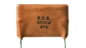 |
| Silver Mica Capacitor |
This type of capacitor is not as widely used these days. However they can still be obtained and are used where stability of value is of the utmost importance and where low loss is required. In view of this one of their major uses is within the tuned elements of circuits like oscillators, or within filters.
Supercap : Super capacitors with capacitance levels of a Farad or more are now becoming more commonplace. These super capacitors are generally used for applications like memory hold up and the like.
 |
| Supercap |
They are too large for use in most circuits and their frequency response is limited, but they make ideal hold up capacitors, being able to provide residual current and voltage to retain memory for periods when power may be removed.
Comments
Post a Comment
Do not enter any spam link in the comment box.