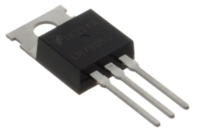
MOSFET stands for Metal Oxide Silicon Field Effect Transistor or Metal Oxide Semiconductor Field Effect Transistor. This is also called as IGFET meaning Insulated Gate Field Effect Transistor. The FET is operated in both depletion and enhancement modes of operation. The following figure shows how a practical MOSFET looks like.
Construction of a MOSFET
The construction of a MOSFET is a bit similar to the FET. An oxide layer is deposited on the substrate to which the gate terminal is connected. This oxide layer acts as an insulator (sio2 insulates from the substrate), and hence the MOSFET has another name as IGFET. In the construction of MOSFET, a lightly doped substrate, is diffused with a heavily doped region. Depending upon the substrate used, they are called as P-type and N-type MOSFETs.
The following figure shows the construction of a MOSFET.
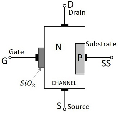
The voltage at gate controls the operation of the MOSFET. In this case, both positive and negative voltages can be applied on the gate as it is insulated from the channel. With negative gate bias voltage, it acts as depletion MOSFET while with positive gate bias voltage it acts as an Enhancement MOSFET.
Classification of MOSFETs
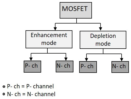
Depending upon the type of materials used in the construction, and the type of operation, the MOSFETs are classified as in the following figure.
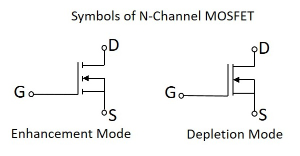
After the classification, let us go through the symbols of MOSFET.
The N-channel MOSFETs are simply called as NMOS. The symbols for N-channel MOSFET are as given below.
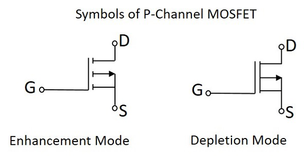
The P-channel MOSFETs are simply called as PMOS. The symbols for P-channel MOSFET are as given below.
Now, let us go through the constructional details of an N-channel MOSFET. Usually an NChannel MOSFET is considered for explanation as this one is mostly used. Also, there is no need to mention that the study of one type explains the other too.
Comparison between BJT, FET and MOSFET
Now that we have discussed all the above three, let us try to compare some of their properties.
| TERMS | BJT | FET | MOSFET |
|---|---|---|---|
| Device type | Current controlled | Voltage controlled | Voltage Controlled |
| Current flow | Bipolar | Unipolar | Unipolar |
| Terminals | Not interchangeable | Interchangeable | Interchangeable |
| Operational modes | No modes | Depletion mode only | Both Enhancement and Depletion modes |
| Input impedance | Low | High | Very high |
| Output resistance | Moderate | Moderate | Low |
| Operational speed | Low | Moderate | High |
| Noise | High | Low | Low |
| Thermal stability | Low | Better | High |
So far, we have discussed various electronic components and their types along with their construction and working. All of these components have various uses in the electronics field.
Comments
Post a Comment
Do not enter any spam link in the comment box.