Basic Electronic Components

Resistors :

resistor is a component that resists the flow of current. It’s one of the most basic components used in electronic circuits. If you put resistors next to a penny, you get an idea of how small they are.
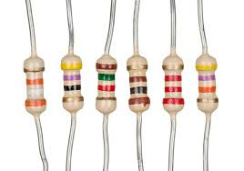
Resistor
Resistors
Resistors come in a variety of resistance values (how much they resist current, measured in units called ohms and designated by the symbol Ωand power ratings (how much power they can handle without burning up, measured in watts).

Capacitors :

Next to resistors, capacitors are probably the second most commonly used component in electronic circuits. A capacitor is a device that can temporarily store an electric charge.
Capacitor
Capacitors
Capacitors come in several different varieties, the two most common being ceramic disk and electrolytic. The amount of capacitance of a given capacitor is usually measured in microfarads, abbreviated μF.

Diodes :

Diode
Diode
diode is a device that lets current flow in only one direction. A diode has two terminals, called the anode and the cathode. Current will flow through the diode only when positive voltage is applied to the anode and negative voltage to the cathode. If these voltages are reversed, current will not flow.

Light-Emitting Diodes :

LED
LED
light-emitting diode (or LED) is a special type of diode that emits light when current passes through it.

Transistor :

                     
Transistor
Transistor
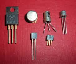
transistor is a three-terminal device in which a voltage applied to one of the terminals (called the base) can control current that flows across the other two terminals (called the collector and the emitter). The transistor is one of the most important devices in electronics.

Integrated Circuits :


IC
IC
An integrated circuit is a special component that contains an entire electronic circuit, complete with transistors, diodes, and other elements, all photographically etched onto a tiny piece of silicon. Integrated circuits are the building blocks of modern electronic devices such as computers and cellphones.


Comments

Popular Posts

Conductance: What is it? (Definition, Units & Formula)

Conductance: What is it? (Definition, Units & Formula) What is Conductance? Conductance (also known as electrical conductance ) is defined as the potential for a substance to conduct electricity Conductance is the measure of how easily electrical current (i.e. flow of charge) can pass through a material. Conductance is the inverse (or reciprocal) of electrical resistance, represented as 1/R. To have a better understanding of conductance, one must recall the resistance of an object. In a qualitative sense, the resistance tells us how difficult it is for an electrical current to pass. The resistance between two points can be defined in the quantitative sense as the difference in voltage that is needed to carry a unit current across the two specified points. The resistance of an object is represented as the ratio of the voltage across something to the current passing through it. The resistance is measured in Ohms. The conductance of a component is a determination of how quickly curre

MOSFET Symbol

MOSFET stands for Metal Oxide Silicon Field Effect Transistor or Metal Oxide Semiconductor Field Effect Transistor. This is also called as IGFET meaning Insulated Gate Field Effect Transistor. The FET is operated in both depletion and enhancement modes of operation. The following figure shows how a practical MOSFET looks like. Construction of a MOSFET The construction of a MOSFET is a bit similar to the FET. An oxide layer is deposited on the substrate to which the gate terminal is connected. This oxide layer acts as an insulator (sio 2  insulates from the substrate), and hence the MOSFET has another name as IGFET. In the construction of MOSFET , a lightly doped substrate, is diffused with a heavily doped region. Depending upon the substrate used, they are called as  P-type  and  N-type   MOSFETs . The following figure shows the construction of a MOSFET . The voltage at gate controls the operation of the MOSFET . In this case, both positive and negative voltages can be

Difference between Core Type and Shell Type Transformer

Difference between Core Type and Shell Type Transformer The main difference between Core type and Shell Type Transformer is the constructional difference of their core and winding arrangement. In core type transformer, the magnetic core consists of two limbs and two yokes whereas in Shell type transformer, there are three limbs and two yokes. In core type transformer , the HV (High Voltage) and LV (Low Voltage) winding are wound on both the limbs. The winding are wound in such a manner to minimize the leakage flux. For this purpose, first LV winding is wound over which HV winding is wound. This also have advantage of lesser insulation requirement for having insulation between the LV winding and the core. Figure below shows a simple diagram of core type transformer. Shell Type Transformer: In Shell type transformer, the winding are interleaved or sandwiched on the central limb as shown in figure below. The LV winding is placed near the yoke and its size is made half of that of other win