
Starting of Induction Motor

Starting of  Induction Motor

A three phase Induction Motor is Self Starting. When the supply is connected to the stator of a three-phase induction motor, a rotating magnetic field is produced, and the rotor starts rotating and the induction motor starts. At the time of starting, the motor slip is unity, and the starting current is very large.

The purpose of a starter is not to just start the motor, but it performs the two main functions. They are as follows.

  • To reduce the heavy starting current
  • To provide overload and under voltage protection.

The three phase induction motor may be started by connecting the motor directly to the full voltage of the supply. The motor can also be started by applying a reduced voltage to the motor when the motor is started.

The torque of the induction motor is proportional to the square of the applied voltage.Thus, a greater torque is exerted by a motor when it is started on full voltage than when it is started on the reduced voltage.

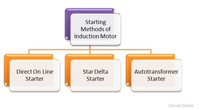
There are three main methods of Starting of Cage Induction Motor. They are as follows.

Block-Diagram-Of-Induction-Motor


Direct On Line Starter

The direct on line starter method, of an induction motor is simple and economical. In this method, the starter is connected directly to supply voltage. By this method small motors up to 5 kW rating is started to avoid the supply voltage fluctuation. 

Star Delta Starter

The star delta starter method of starting three phase induction motors is very common and widely used among all the methods. In this method, the motor runs at delta connected stator windings.

 Auto Transformer Starter

The Auto transformer is used in both the type of the connections, i.e., either star connected or delta connected. The auto transformer is used to limit the starting current of the induction motor.

The above three starters are used for cage rotor induction motor.

Slip Ring Induction Motor Starter Method of Starting Induction Motor

In the Slip Ring Induction Motor  starter, the full supply voltage is connected across the starter. The connection diagram of the slip ring starter induction motor is shown below.

Slip-Ring-Induction-Motor
Slip Ring Induction Motor

 Full starting resistance is connected and thus the supply current to the stator is reduced. The rotor begins to rotate, and the rotor resistances are gradually cut out as the speed of the motor increases. When the motor is running at its rated full load speed, the starting resistances are cut out completely, and the slip rings are short-circuited. 


Comments

Popular Posts

MOSFET Symbol

MOSFET stands for Metal Oxide Silicon Field Effect Transistor or Metal Oxide Semiconductor Field Effect Transistor. This is also called as IGFET meaning Insulated Gate Field Effect Transistor. The FET is operated in both depletion and enhancement modes of operation. The following figure shows how a practical MOSFET looks like. Construction of a MOSFET The construction of a MOSFET is a bit similar to the FET. An oxide layer is deposited on the substrate to which the gate terminal is connected. This oxide layer acts as an insulator (sio 2  insulates from the substrate), and hence the MOSFET has another name as IGFET. In the construction of MOSFET , a lightly doped substrate, is diffused with a heavily doped region. Depending upon the substrate used, they are called as  P-type  and  N-type   MOSFETs . The following figure shows the construction of a MOSFET . The voltage at gate controls the operation of the MOSFET . In this case, both positive and n...

What is Electrical Switch

What is an Electrical Switch : An electrical switch is any device used to interrupt the flow of electrons in a circuit. Switches are essentially binary devices: they are either completely on (“closed”) or completely off (“open”). There are many different types of switches, and we will explore some of these types in this chapter. Learn the Different Types of Switches : Switches can be of mechanical or electronic type, Mechanical switches  must be activated physically, by moving, pressing, releasing, or touching its contacts. Electronic switches  do not require any physical contact in order to control a circuit. These are activated by semiconductor action. Mechanical Switches : Mechanical switches can be classified into different types based on several factors such as method of actuation (manual, limit and process switches), number of contacts (single contact and multi contact switches), number of poles and throws (SPST, DPDT, SPDT, etc.), operation and ...

Thyristors Working

Thyristor Tutorial In many ways the Silicon Controlled Rectifier, SCR or just  Thyristor  as it is more commonly known, is similar in construction to the transistor. It is a multi-layer semiconductor device, hence the “silicon” part of its name. It requires a gate signal to turn it “ON”, the “controlled” part of the name and once “ON” it behaves like a rectifying diode, the “rectifier” part of the name. In fact the circuit symbol for the  thyristor  suggests that this device acts like a controlled rectifying diode. Thyristor Symbol However, unlike the junction diode which is a two layer ( P-N ) semiconductor device, or the commonly used bipolar transistor which is a three layer ( P-N-P, or N-P-N ) switching device, the  Thyristor  is a four layer ( P-N-P-N ) semiconductor device that contains three PN junctions in series, and is represented by the symbol as shown. Like the diode, the Thyristor is a unidirectional device, that is it ...